
Introduction.
Truth be known a IC9700 was not in my radio budget. So being an owner of the IC9100 and very happy with its performance, also has the ability to do as much as the IC9700 and more, I decided to add the only item the IC9100 missed, a pan-adapter(this radio is a shack rig, never goes on field days). Well the first thing was find one, budget AU$100 approximately. So I hit the net, typed in pan adapter IC9100 and bobs KD2C (David https://kd2c.com ), had this little PC board which could accommodate the four bands HF,VHF,UHF and SHF, nothing was mentioned about D Star and digital modes .
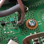
Figure 1- PAT-V-9100 Module
As I had other radios to do these modes, I bought it which arrived 2-3 weeks later. Easter 2019 came quick, so lots was happening, and I had lifted the lid on the IC9100 and it looked rather daunting so I closed the lid and got on with life. Easter Monday came around and I opened the radio had a further look a couple of cups of tea and started. PC board came complete, all that had to be done was solder red and black power wires one RG-316 output coax to one end, four RG-316 coax cables to the other end, job done.
Next find all the soldering points on each band to connect these coax cables, with the help of the extremely well documented paperwork from KD2C, they were all found. After a few more cups of tea I got the soldering iron to temperature and started, to my amazement the points to solder required less effort than imagined leaving me with that feeling we all get after a successful outcome.
Power to the board was also well documented, with a quick connection to a 10 volt track. A hole needed to be drilled in the chassis for the SMA outlet, for the SDR. I tidy the cabling replaced the covers and pushed the all important power button. No smoke, all powered up as per normal and the PC connection into the SDR dongle, all worked to plan. Also, most other types of radios are supported by David’s boards.
Review.
When the kit was assembled and installed (extensive detailed instructions provided), it was time to ask for a check of connections and the operation of the radio with the PAT fitted.
When asked to review the installation, George VK4AMG was pessimistic about the TAP connection points on the top of the VHF through SHF tuned circuits and doubted if a two stage source/emitter follower could have the required frequency response (to 1300 MHz). The connection from the TAP point to the module by 30+ cm of RG142 coax cable (20+ pF) and the shield connected only at one end also caused concern about detuning and coupling noise into the front end of the receiver.
A PIN diode switch has been added to the front end of the PAT amplifier in attempt to provide automatic selection of the active receiver in the IC9100. There is no termination on the PIN diode switch. A normal value would be conflict with the supposed high impedance of the amp. The DC voltage at most of the recommended tap points is the tuning voltage for the front-end bandpass circuits and is insufficient to provide effective switching of the PIN diodes with or without a terminating resistor.
Figure 2 and 3 show the frequency response of the PAT-V-9100 module with and with biased PIN switches.
The Hi-Z section is useful as an IF/RF tap to about 50 MHz. As an RF tap for a VHF / UHF radio it is a 20+ dB attenuator. With any detuning of the RF tuned circuits due connection of the PAT-V-9100, the radio sensitivity is degraded and an externally connected SDR may only show signals of S7 or better.
Figure 2 – PAT-V-9100 Freq Response – No bias on input diodes
Figure 3- PAT-V-9100 One input diode forward biased, Others reverse biased
George has previously used applied PGA-103 LNA modules (Minikits PGA-103 LNA kit or eBay “0.05-4GHZ Low Noise Amplifier LNA RF Broadband Amplifier 23dB High Linearity 5V”) with a SMD attenuator / splitter inserted in the VHF / UHF RF cables or internally in the IC910 23 cm module. In addition to providing a high-performance TAP point, the LNA lifts the performance of the IC910H receiver.
Figure 4- LNA and attenuator providing a 23cm TAP in IC910H
The options for combining four of these modules to cover the IC9100 bands are being evaluated and will be published when this project is complete.